(Untitled)
Is your dishwasher part of the micro-plastics waste problem?

(Untitled)
Sea water may soon provide freshwater to coastal drought communities.
Introducing Deep Sea Reverse Osmosis


Insulated Concrete Form made from hemp
This brick closely resembles the nexcem (Durisol) brick that I used. While shipping costs and the carbon footprint associated, made the use of the nexchem brick on BC uniquely, have a similar brick made locally would be a game changer.

Parkland makes first batch of 'bio-fuel'

Largest Plastics Recycling Facility in the World - Enter Site Zero
Once built, Site Zero will be the largest plastics recycling plant in the world, able to process 200,000 Metric Tons yearly.
This site will elevate their ability to sort from 4 types of plastics to 12 different plastic materials. They envision being able to recycle 95% of the waste plastics (up from only 47%).
Well done Sweden Plastic Recycling!!!
They have set a high bar for other countries to follow. Now we just need to work on getting more of our plastics actually sent to recycling, instead of just being trashed or discarded, where it can end up in the oceans and waterways.

Start the recycling process at home! With One Clear Drop, it is easy.
I watched the first video about the plastic in the great pacific garbage patch, back in 2009, and since that time I have generally not thrown out ANY plastic. This even included plastics I would come across when say, eating out or having fast foods.
I instead have collected it and stored it till I could take it in for recycling.
This has even included plastics not taken by local municipality. For these plastics, I pay for them to be recycled by http://pmdrecycling.com.
I regularly follow and support https://theoceancleanup.com/ and am excited about their river interceptors. They are concentrating on stopping the plastics BEFORE they get into the ocean.
But what if you could be part of the solution in your own home.
Even though I am a strong promoter of recycling and reducing our plastic use (especially single-use), I have to admit that the storage of the plastics is an issue.
I dedicate a large bin in the kitchen and then a large schafer sized bin in the garage. But these are always a mess as the plastic pushes itself back out as it expands after depositing. It takes up a lot of room and is difficult to get into a manageable package size to take to recycling.
I recently came across an consumer appliance from One Clear Drop, that pre-processes film plastics into a tight, partially melted, block.
With the SPC (Soft Plastic Compactor), Once Clear Drop is allowing the consumer to be part of the pre-processing solution. These ‘bricks’ would reduce the volume needed at the recycling drop off centres, prevents cross contamination, prevent recycling conveyor maintenance, and reduce bacterial growth on plastics waiting for processing.


Electric Ambulance
Hey folks – sorry for the long absence! Still building the house 🙁 Hoping to be in by February.
But came across this article sent by a friend. This would be an awesome upgrade!

Time to stop plastic pollution is now!
BC Governement looks at banning one use plastics.
Please have your say and complete this short survey. The time is now, to stop the production of one use plastics in our Province.
https://cleanbc.gov.bc.ca/plastics
Plastic - The menace that we all must face
Sorry folks – I have not been very active on this blog while I continue the long process of building my own house (theEnclosure.ca). But I came across this article and felt needed sharing far and wide.
Pacific Plastic Dump Far Larger Than Feared Study

I first became aware of the build up of plastics in the Pacific Ocean back in 2007 after watching some YouTube videos from Captain Charles Moore documenting his trip to the Pacific Gyre (video) .
At the time there was a lot of surface plastic, but the more worrisome issue was the micro plastic that was invading the marine food chain. It was shocking to revisit news of this area and see how much larger the region was compared to 10 years ago.
We all need to do our part to help. On a previous posting I talked about ensuring I did not throw out ANY plastic. I am proud to say that I am still about 95% compliant with this commitment. All plastic I generate at home and even on the construction site is separated and taken to recycling. I also try to use re-usable bags for the vast majority of my shopping. The one area I do occasionally fall short is when dining out at fast food locations. I do not always bag up the plastic to bring home and recycle. I will try harder!
The medical and science community are now finding micro plastics embedded in us! This article covers research performed in Belgium that shows these micro plastics consumed are becoming embedded in our flesh.
We all need to do our part and do better. From reducing the volume of single use plastics to ensuring the plastics we do use are properly recycled at the end of their life span.
Primer - Anchoring Framing to Foundation
Hey folks, thanks so much for continuing to visit this blog, even though my activities have been 100% occupied with building theEnclosure.ca and the last article I posted here was all the way back in February. As promised, I intend to post more technical themed articles to this blog and use the project journal on my build site for my day to day thoughts and tribulations on building an energy efficient home.
So, it is time for an article that provides a primer into Anchor Bolts. In the days of old, a concrete placing crew would just embed a 1/2″ anchor every 4ft or so and call it a day.
Most dwellings had either small cripple walls placed above the foundation wall or had the floor joist assembly sitting right on top of the sill plate. Both of these were able to easily accommodate the location of the anchor bolt with little effort.
Modern construction has changed a great deal in this regard. In areas of high seismic activity, the location of anchor bolts is critical to meet either the code prescriptive path to seismic rigidity, or an engineered path. For us @ theEnclosure.ca, we were forced by the Municipality to upgrade from the Building Code prescriptive path and instead use the prescriptive path laid out in Canadian Wood Council’s Engineering Guide For Wood Frame Construction Part C.
In Part C, the requirements for anchor bolts for my region (Lower Mainland BC, Canada) are laid out as follows:
– There must be two bolts minimum per braced wall (seismic) panel
– The bolts must be installed no more than 1.64 ft from each end of a foundation wall
– Bolts must be installed every 7’10”
– 1/2″ embedded 4″ into the concrete
It is interesting, in contrast, the BC Building Code required 1/2″ anchor bolts spaced no more than 5’6″ apart (7’10” was allowed but only for 5/8″ bolts).
So now, it is critical that prior to your concrete crew coming, all anchor bolt locations are marked out on the form work to comply with the newer seismic regulations. It is also important that the setback from the foundation wall face is identified to ensure that the anchor bolt will miss objects like rimboards (engineered wood) or rim joists (real wood).
For our construction, we had an added level of difficulty surrounding the placement of these bolts. Our design includes a dropped floor assembly that is flush with outside grade in order to meet the requirements of SAFERHome Society. But code still requires that the foundation project 6″ above grade (BCBC 9.15.4.6) which results in a concrete foundation stub projecting above the floor surface.
 |
| Building code requires the foundation to extend 6″ above grade to prevent wood components from rotting. On a floor assembly that is flush with grade (dropped), this results in a concrete stub extending above the floor. |
As my wall framing was then mounted directly to the foundation, it was critical that in addition to meeting the seismic requirements, I also had to ensure that they were placed to miss my wall stud framing. I was about 85% successful in this endeavour. The rest had to be cut off and replaced with drill-in anchors, which my inspector stated would accept for a limited qty.
SO, you have all your anchor bolts embedded at the right locations, lets add the washer and nut and call it a day – right? From a code perspective, you would be right. But there is a best practice when it comes to anchor bolts. I have to thank one of my Home Inspection client’s Nikolas for this information.
Turns out that the washer makes a perfect wedge to split the plate apart during an earthquake as the bolt bends under the shear loads exerted by a quake. Who knew??? I reviewed the article that Nikolas sent and written by Howard Cook titled “The importance of Plate Washers”
Howard retrieved the following graph from the Los Angeles Building and Safety department (a group that knows a little bit about earth quakes don’t you think!)

You will see that at every point along the graph, that the wall using a plate washer deflected less for a given force when compared to the round cut washer. By introducing a 3″ x 3″ plate, you are able to better prevent the bolt from bending under shear and preventing the splitting of the sill plate. The mentioned article includes a sketch by Nels Roselund that shows the reactions involved.

Based on this information, we elected to use the 3″x3″ plates on The Enclosure but did run into problems on many of the bolt locations. Unless the anchor bolt was dead centre in the 2×4 sill plate, there was not enough room between the sheathing and the bolt or the inside face of the stud and the bolt, to place the plate. SO we used the plates for as many of the bolts as possible and then just the standard washers for the rest.
 |
| Just enough room for plate between bolt and sheathing |
 |
| This bolt was placed too far outboard to slide the plate on. |
Howard has also published an article titled Bolting: Attachment Of The Mudsill To The Foundation for those interested in additional reading. Nikolas also forwarded the article QuakeCheck: When the big one comes, will your home be “Safe enough to stay?” which made for a great read to further brush up on this subject and how to address it.
If you have an older home, it may be time to upgrade your anchorage. Is it not worth a few hundred dollars and one day of your weekend to make your family as safe as possible in a seismic event?
Thanks for visiting!
Mould – The Black Scourge (And how to eradicate it)
As most of those that frequent this blog or my build website know, I am already 2 years into the process of building a house for myself and my wife, by myself, and still have a LONG way yet to go.
With the famous proverb “You can have it Fast, Cheap, and Good – Pick Any Two”, I have elected to build cheap and good (actually very good), and therefore, I am far from fast. Further delays with broken shoulders and bulged discs in lower back, and progress at times has literally been brought to a crawl! This resulted in a partial structure being exposed to the winter elements because I was unable to proceed fast enough to allow framing and roof completion during summer of 2015.
Now, I have taken great pains to keep this partial structure dry during construction, first with a large overhead tarp (Big Ass Tarp – B.A.T.), and then with smaller tarps closer to the floor deck when the B.A.T. was shredded in a wind storm in Dec 2014. And generally I have been successful in keeping bulk rain water off the structure. So imagine my horror last December when I finally installed some construction lighting in the now very dark basement, only to turn the lights on and find I had mould and staining fungi all over my engineered beams. Quite frankly, I was devastated. It also did not help that I am allergic to the stuff and started getting chest issues from working in the basement.


Left – Big Ass Tarp (B.A.T.) measured 60′ wide x 80′ Long Right – Current Configuration of Smaller Tarps have kept all bulk water off structure.
 So what went wrong? If it did not get wet from rain, why was there an issue?
Well, in all of my careful attention to what was falling from above, I did not focus ANY attention to what was rising from below.
You see, I basically have built my house above a temporary swimming pool. Granted a very shallow swimming pool, but a pool just the same. The whole structure is built over a crushed gravel base. Even the footings have a minimum of 6″-8″ of consolidated 3/4″ crushed rock beneath. This will provide the drainage plane under the yet to be poured floor slab, and there lies the problem. There is no concrete floor slab or sub slab poly keeping the moisture within the gravel drainage at bay. There is a HUGE surface area (approx 1750 sq. ft.) of water that may only be 1/4″ deep at times, but that is still a lot of moisture that can evaporate off and create a very high humidity environment in the basement. Add to this all of the construction moisture present in the still curing foundation walls, the recently poured suspended garage slab, and from the storage of various salvaged wood I used for scaffolding (and therefore exposed to rain and saturated) that was stored in the basement (ironically to dry out). When I started measuring the humidity after discovering the problem, I was in the very high 80’s for RH% and clearly had been so for several months.
 |
Now, realize at the time, that the basement was still very wide open from a ventilation stand point. There was a 4’x8′ door opening in the side of the foundation to service the basement exterior walk up stairs, and there is the stair opening in the floor assembly that will service the interior stairs to the basement. So air movement was not an issue, but the humidity was still too high. Add to this the crazy dew-points we have in North Vancouver, and the opportunity for condensation to form on the structure was high.
As an example, photo at right shows ice forming on UNDER side of tarp due to tarp surface cooling below
dew-point of ambient exterior air due to night sky radiation. This was a
fully ventilated area. As you can see in the background, there is no
walls.
Do you still believe ventilation is the answer for attic mould???
The next factor is that any engineered wood (like my PSL beams) is more susceptible to wetting. The glues in these beams readily absorb moisture, as does the heart wood often utilized in the manufacture of engineered wood. The result was that my beams had reached a fibre saturation moisture content (roughly 32% WM), which is the point needed to inoculate wood for fungi growth. After inoculation, the moisture content only needs to be above 19% for the fungi to continue growing.
So, in the end, it was the humidity from below that bit me, not the moisture falling from the sky above. So now what? What are the possible steps to remediate?
Well, I can tell you that in a lot of construction, it would just be covered over with drywall and ignored. And by rights the structure should be below 19% WM before covering up with drywall so technically the mould would be dormant by then. But what happens if the humidity in the home is too high for extended periods of time (say there is a bathroom with a shower nearby, or the owner likes indoor plants). A relative indoor humidity above 70%, for an extended period of time, could lead to the wood wetting up past 19% again. With my allergies, leaving it was not a good idea, so I set out to remediate it.
I talked with some individuals in the building envelope industry including a group doing an attic mould remediation study. I also had studied this subject intensively in the past, because as a previously practicing home inspector, I always struggled with the right information and advise to provide clients, when the inspected home had a mouldy attic. I knew that you had two tasks: First remove the evidence of the fungi contamination, then kill or render dormant the actual fungi spore. If you only killed off the spore, you would still be left with the staining which would present as a defect to the consumer, but more importantly would not allow you to identify if any new fungi growth occurred in the future, as it would be too hard to spot new staining overtop of the old staining.
The group doing the study recommended a cleaning protocol utilizing one of the following three options:
1) Scrub surface with soap and water
2) Scrub Surface with a mild bleach solution
3) Spray Surface with Concrobium Mold Control (Commercial product – not the stuff you buy in Big Box Stores)
This cleaning protocol was to ‘reset’ the appearance of the infected product before treating and preventing future fungi growth.
 Well, I can report that all three strategies were woefully inadequate on the rough and porous surface of an engineered beam. 1 & 2 may work on a surface like painted drywall or even a real wood surface like a 2×4, but on the engineered wood they were generally ineffective. Photo at left shows a beam after being treated with both the soap & water solution and then a bleach solution. While the cleaning removed some staining intensity, it is still clearly visible.
 I then tried option 3 and sprayed the surface of all beams with the Concrobium Mold Control, which is supposed to have some stain removing capabilities. In my tests, it was even less effective as the soap and water or bleach solutions at removing the staining.
Photo at right represents the results 48 hours after treatment. Unfortunately, I did not have a clear ‘before’ photo but this beam started with substantially less staining than say the beam in the above photos. The staining present after treatment was very similar to the start point prior to treatment.
With all three cleaning protocols a bust, I regrouped and brought out the big gun. Concrobium also make a product called Mold Stain Remover. This is a mixture of Sodium carbonate peroxyhydrate (basically granular hydrogen peroxide – used for instance in non bleach cleaners like OxiClean) and Propylene Glycol Diacetate (a solvent, presumably to help allow the cleaner to penetrate past the surface of the material to be cleaned). Together they pack a punch but generally break down into biodegradable by-products and personal protective gear required for application is minimal. Rubber gloves are a good idea as it can irritate skin and some form of eye protection is recommended as it does burn if you get any in your eyes. It also gives off a strong acid like odor when mixed, but this dissipates in less than 24 hours after spraying.
I have now sprayed the product twice in different areas of the basement. The first time I mixed it with the hottest water out of the tap at our rental suite and all of the crystals generally dissolved. The second time I specifically measured the temp and brought the starting point down to 100F (max recommended). But by the time I sprayed, it had cooled to 70F and I found a lot of the crystals on the second application had not dissolved and were still in bottom of mix bucket. So I would be inclined to start with water slightly above 100F, so that after mixing and by the time you load the sprayer you are within the required 80-100F application range. Also while writing this entry, I re-reviewed the application instructions and now realize you are supposed to add the crystals (part 1) to the warm water FIRST and stir to dissolve BEFORE adding part 2. I added both together and then stirred on the second application (do not remember what I did on the first), this may have effected the ability for the crystals to fully dissolve in the mixture. Regardless, the results were extremely impressive!


Photos on left are before treatment with the Mould Stain Remover but remember after treatment with the Mold Control product. The right photos are after 1 treatment of the Mould Stain Remover. As you can see, the stains are gone on a majority of the surfaces, but there was still locations where the staining was present like the following images.


What I suspect happened at these locations is that they did not get wet enough for long enough when sprayed. The instructions state that the surface is to stay saturated for 60 mins. SO I mixed up a second batch a few weeks later and have now all but eradicated the stains As is shown in the following photos.


Photos at left prior to treatment with the Mould Stain Remover but after previous treatment with Mold Control. This elimination of the mould staining generally happened in the first 60 minutes after spraying.


But the best example is this spare beam I have sitting on my garage floor. Photo on left was after using 3% H2O2 which although dimmed stains did not remove them. Photo on right shows the complete removal of stains with the Concrobium Mould Stain Remover.
So there you have it. A easy, fast, and relatively affordable method to remove mould stains from engineered wood. I will now spray all the beams with the Mold Control product to kill or make inert any remaining mould spores and prevent future growth. I will leave the test beam above untreated so that I can determine how quickly the mould would come back if left untreated. I have to say, it was a HUGE physiological pick-me-up to walk into the basement after the second treatment and not be able to see any stains remaining. Now I can count on a healthy basement with no future issues.
Zero Waste
A walk down Bea Johnson’s Path to Sustainable Living.
Life Without A Trashcan: A Look Inside the Zero Waste Home

Bea has managed to reduce her family’s garbage YEARLY output to the mason jar. She does this by generally buying in bulk and using her own glass or cloth containers.
This is truly impressive and a example to try and follow. While I have reduced the waste, that goes to landfills, in my home to about 2-3 garbage bags a year, I do end up with a LOT of packaging that must be recycled each week. I will buy her book and try to start incorporating some of her ideas in my lifestyle going forward.
We need new testing procedures for insulation to show the full story.
Hey folks,
Sorry it has been so long since last posting. Been busy on the house construction. I do keep a project journal and update it weekly at theEnclosure or you can click on the updates listed on the right side of this blog.
I should have a technical update for you soon where I review all of the products/methods I used in constructing my basement. In the mean time, I wanted to expose my readers to an excellent article written by Rockford Boyer of Roxul. In it, he identifies the risks of using a set insulation R-Value in your modelling as with many products, the resistance to heat loss changes depending on temperature.
The Theory of R-value Relativity: The impact of thermal conductivity on building enclosure durability
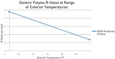
One of the things that caught my eye was the danger faced, when modelling in WUFI, of getting erroneous results. I have extracted two of the tables and shown below. As you can see, there is a huge difference between the reported results. Fig 1 is using the material from the WUFI database and Fig 2 is re-running the material with a material properties entered manually and based on actual testing. The risk if you are not aware of these issues, is designing an assembly that in real life will act nothing like your model. If you are lucky it will be better than the model but in most cases it will mean you have a higher risk in your assembly than designed for. A risk that may overwhelm the assemblies ability to recover.
 |
||
| Fig. 1 Extrapolated R-Value based on WUFI material database. |
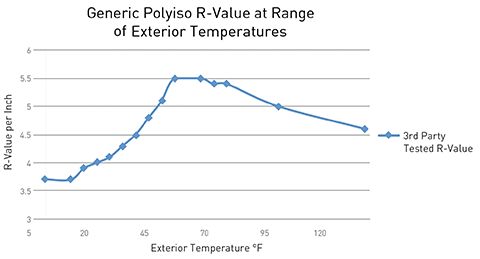 |
| Fig.2 Extrapolated R-Value based on actual lab testing |
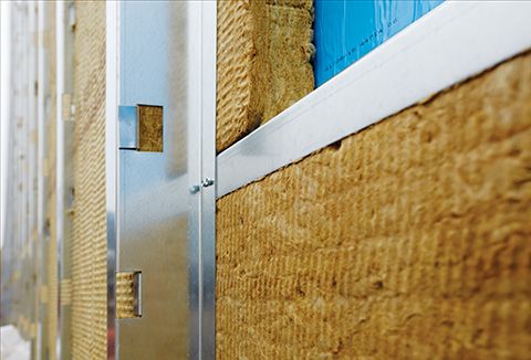
Insulating a Durisol ICF Foundation
Hey folks, sorry for the time span since the last post. I have been concentrating on keeping my building journal up to date.
As I recently have had some free time due to yet another set of medical setbacks, I recently finished editing and uploading a video showing my process of adhering the Roxul ComfortBoardIS mineral wool insulation to my ICF foundation.
The Soprema Colphene Torch’N Stick membrane would typically be used on a site formed concrete foundation, but because I am using a ICF product from Durisol (made from mineralized wood fibre and cement slurry), I too could use this torch on membrane (a process that would destroy conventional EPS foam ICF forms). The ‘tacking’ of the insulation to the membrane is only a light mechanical bond and is only suitable for a temporary support of the insulation (or dimple board and other protection sheets) until the backfill takes place. You would not be able to use the method for a permanent attachment in an above grade assembly.
Once the insulation was attached, I then fastened dimple sheet to the insulation, installed a granular drainage plain, geotextile, and then compacted backfill. You can read about these steps on my “coming out of the hole” journal entry.
The overall foundation assembly will have multiple layers of safety and will be very durable, but the installation is costly and very time consuming. I can understand why many of these steps are not incorporated into most residential construction. But then, most residential below grade basements are wet to some degree. As my friend Murray Frank often says “You never hear a comment ‘It smells as good as a basement'”.
Thanks for visiting folks. I will hopefully post a review of all the products I have used to create my foundation walls within the next few weeks. A majority of the products get a thumbs up from a technical standpoint, but one in particular is a two thumbs down with extreme prejudice. I encourage you to subscribe if you want to be notified of when this review is posted.
Air Leakage of Old House - Does it matter?
*** Update – Upon further reflection of this topic, I do feel there is one additional reason to perform energy upgrades and discuss it in my project journal http://www.theenclosure.ca/windy-house ***
This blog entry will analyze the air leakage of a 1954 house and relate that to the energy use and durability of the house.
Before I started tearing down my 1954 single storey 1500 sq ft bungalow to make way for theEnclosure.ca, I decided to have the house tested for air leakage by Michael and Deborah from H&H small home solutions inc (hhsss at shaw dot ca). H&H typically perform leakage testing to determine the EnerGuide rating for new construction, so this was going to be a new experience for them (and their blower door).
They came by in late March of 2014 after I had moved out but before I had completely emptied the house and before any deconstruction had been performed. The house was prepped by sealing the wood burning fireplace insert, range hood, and the through-wall mailbox before setting up the blower door.
We first ran the door in a B configuration and were unable to get up to the final test pressure of -50 Pa. But even in this configuration we got some scary results. I had not really made any great attempts to air seal this house over the years. There was weather stripping on 1 of the 3 doors, and the cedar siding had each coarse sealed to the next and the siding sealed to most of the window and door frames. But no attempts had been made to seal the interior interface with the attic plane and 1 of the doors had a cat door in it and the main door itself had very large gaps around it.
Prior to starting the test I had predicted an air leakage around 8-10 ACH (Air Changes per hour) @ -50 Pa, but early in the test we could tell it was going to be well above this. Deborah could tell just from the sound the fan was making (there previous worst house they tested was 11 ACH @ -50 Pa which was scary as it was new construction).
Right off the bat we reached 28 air exchanges at only -15 Pa! To give you an idea, 15 Pa relates to a wind speed of only 11 MPH. In the fall, I regularly recorded winds speeds on the property at this speed or higher so during those events all of that CONDITIONED air in the house was potentially changing over 28 times every hour. That is a lot of extra load on the heating plant and also explained the drafts my wife typically was feeling.
Over the next hour or so we tested at various configurations until we ran the fan at full open configuration (no restrictor plates). Only then could we get enough air volume to allow us to reach the target test pressure of -50 Pa. AT the full test pressure we recorded an air leakage of 21.74 ACH -50Pa.
Now wait, some of you may have noticed that that is less air leakage than what we observed at only -15 Pa. How is this possible you say?
Well, it is actually quite common. As more and more negative pressure is placed on a dwelling, the two surfaces on each side of an air path (leak) can start to come together. Eventually they can close up tight and stop that leak. This why I have a bit of an issue (actually quite a bit), of testing dwellings at -50 Pa. This relates to a wind speed of 20 Mph which is much higher than some locations would experience on a regular basis and much lower than other locations average wind speeds. As such, it is my opinion that their should be a standard test pressure PER geographical region. This could be a table much like the climate zone charts, but would be based on the average yearly mean wind speeds for a specific area. Homes in higher wind speed regions should be tested at higher pressures than homes in lower wind speed regions.
(Side bar – the reason the wind speed is important is that it is this force that will effect the pressures on a dwelling. Yes a house can depressurize under mechanical ventilation, but these are usually infrequent where wind depressurization or pressurization of the dwelling could occur for months at a time in windy locations).
So – these tests showed that the house was VERY leaky. What does that mean in terms of heating bills, comfort, and building durability.
Heating Bills
The truth is, this air leakage did not really make a huge difference in energy costs. My heating bills (for space and domestic hot water) were typically well under $2000 a year (We are under $2000 for both gas AND electrical use). As I am a heavy bath user, it is safe to say aprox 40% of this was domestic hot water use. This leaves an estimated $1000 in annual space heating costs. That works out to less than $100 a month, or well less than the cost of a weekend dinner out.
We typically had the heat set for 72-73F in the wintertime and basically did not tough the thermostat all year. It was not uncommon for the heat to come on during cold late spring and early fall evenings. We did however use a programmable thermostat that was set to come on at 7 AM, step down to about 65F at 8:30 AM, come back to temp at 4 PM, and step back down to about 68F at 11:30 PM. This was only partially for energy savings. The night time set backs were used because we had hydronic heating through large built-in wall registers (1-2 per room) via a 1980’s gas boiler. The pipes went through and rubbed on the wood sub-floor assembly, so if the heat came on during the night the ‘clicking’ would wake me up. So we partially closed the bedroom door (so cats could still get in and out and not cause another source of nighttime wake-ups) and used an electric oil heater to maintain a comfortable temp in the bedroom.
While air tightness is important, it will not make a huge difference to your pocket book unless you have a very large and leaky house.
Comfort
The air leakage did however make a big difference in occupant comfort and should, in my opinion, be the biggest (and probably only) reason to upgrade an older home. The house was uncomfortable to sit in near any exterior wall in the winter months due to the drafts present. I was quite surprised when I saw how leaky the fixed, but home made, windows in the living room were. The builder had just placed the single pane of window glass against a wood surface and clamped it with a second wood component. At -15Pa, the wind just whistled through these locations. There is no question, that making the house more air tight would have made the house more comfortable.
Durability
Normally when one discusses the reasons for making a dwelling air tight, it is in the context of a ‘modern’ home with current levels of code required insulation. With modern levels of insulation, it is critical to ensure that air leakage does not occur, in order to prevent interior air leaking into the wall or roof assembly and condensing on cold sheathing. Left unchecked, this will often lead to mold and rot within the assembly.
The key here is the qty and location of the insulation. As soon as enough insulation is placed inside of the sheathing to allow the sheathing to cool down below the dew point of the interior air, you now have an assembly with a very high liability should any appreciable amount of air leak into that assembly from the conditioned interior. This is because air currents are the #1 mover of moisture next to bulk water leaks caused by plumbing leaks or incorrectly detailed cladding or roofs that permit bulk rain water entry into the assembly.
But in older houses like the one I took down (which had ZERO insulation in the walls), there is not enough insulation present to block the heat loss from the house enough to allow the sheathing to get to the dangerous dew point conditions. If you never reach the dew point, you can have huge amounts of moisture moving into the wall via air leakage and never have to worry about it because it stays in vapour form and just moves on through either to the outside of the dwelling or back into the inside. There is never liquid water that results from this air leakage. This is the reason why older homes have performed so well over many decades without the presence of air barriers, vapour barriers, or even effective water shedding surfaces. The heat loss has always been enough to ‘cook’ any accumulated moisture out of the assembly.
Conclusion
We have identified in this article that there is not a huge financial penalty for a leaky house. In my case, the costs per month for space heating were under $100/month in what is considered a cold-heating-dominated climate. This $1200 annual investment would not get very far in paying for a deep energy retrofit which typically would cost 10’s of thousands of dollars. Lets say you could reduce the heating load even as much as 75% (purely speculative and most likely could not meet), this would represent $900 annual contribution to renovation costs.
A REALLY cheap stud level renovation for my home (including new windows and doors) would have been at least $60K (going to need to rip out parts of bathrooms and kitchens so most likely will totally renovate those rooms – my budget of $60 assumes very low end cabinets for these rooms).
A very intensive attic floor plane sealing regime would have been at least $15K (not going to do this process without bringing attic up to current insulation levels when done).
At a highly inflated $900 annual savings, these two projects would have a 66 and 17 year payback respectively. The attic plane sealing payback would most likely be much longer as only sealing this plane would probably represent only 50-70% of all air leakage present and therefore there would be reduced energy savings.
And my house did not represent an unusual annual energy bill. This US Energy Summary shows that for the West, the average annual winter heating bill per household varies between $1300 and $800 depending on year.
In the end, due to our really low energy costs, and the likely hood that they will not appreciably escalate for many decades due to Government interference, it makes very little sense to upgrade an existing homes energy performance for personal financial savings. Therefore the type of renovation needed to reduce air leakage or increase thermal performance, only makes sense if the home is being renovated anyway for cosmetic or occupant comfort reasons.
On a separate track – this logic also holds true when analyzing extreme new construction programs like Passive House. The costs to reach passive house levels of energy reduction will not be paid back over the lifespan of the dwelling in most cases. The added detriment of these programs is that the embodied energy of the insulation products built into these dwellings also do not have a pay back within the lifespan of the dwelling. Instead for new construction, it makes more sense to build a “Pretty Good House” (coined by Joe Lstiburek) and then use the excess capital available to either contribute to distributed or on-site energy generation.
It is however critical that air leakage be reduced down to a minimum (experts do not agree how little is adequate – but the number is somewhere between 1ACH+/-50 and 3ACH+/-50) for new construction or energy retrofits IF, you have built an assembly with enough insulation inboard of the sheathing to cause the sheathing to cool down to the dew point potential of any leaking interior air. If you build a safer assembly with the insulation outboard of the sheathing (or enough outboard to maintain the sheathing above the dew point potential), then while air leakage is still important to address from an energy loss standpoint (the costs to get it right during construction are minimal and will be paid back by reduced energy usage), it usually will not cause a durability concern for the assembly. This of course is all from the perspective of a heating dominated climate. The direction of flow and order of layers for the assembly are different in a cooling dominated or mixed climate.
Foundation Rebar Installation Primer
Wow – cannot believe it was last November when I last posted to this blog! I promise to start writing more technical posting (as opposed to the daily journal entries found at my building web site).
I posted this on my journal as well, but felt it was important enough to also post here.
I received some feedback to my journal posting yesterday that was
suggesting I should look at the ‘other’ ICF manufacturers if I wanted to
know how Rebar was ‘supposed’ to be placed. I did and the result sure
is scary. Because you are allowed to install ICF walls without ANY
engineering assistance (as long as you meet the building codes
requirements including max unsupported wall height) and therefore
engineering inspection, there is a plethora of miss-information out
there regarding the requirements for rebar reinforcing of an ICF wall.
At
least the BC Building code makes it pretty clear on the requirements,
but I suspect that because the Municipal inspector is not present at
time of pour, these requirements may not be adhered to – at least that
is what is evidenced by one of the discussion forums I visited last
night.
So – lets first look at the BC Building Code requirements.
The
Horizontal rods are to be installed every 2 ft vertically and are to
have 1-3/16″ inside minimum cover (30mm) meaning that the rod is to be
held off the outboard surface of the inside ICF panel to allow 1-3/16″
of concrete to be present on the inside face of the bar.
The
Vertical rods are to be installed per tables BCBC 9.15.4.5 A to C
depending on core thickness and height of wall. The first options calls
for vertical rod placed every 16″ horizontally with again 1-3/16″
inside cover (30mm) minimum.
Obviously both
vertical and horizontal bars are unable to occupy the same plane off
the inside face of the foundation, so the code also specifies a max
cover by stating the bars are to be “located located in the inside half
of the wall section”.
My requirements were
much more stringent because of the height of the wall. The engineer
specified vertical bars every 12″ horizontally and horizontal bars every
2′ vertically. I was not given a range for the vertical bar – it
required 1.5″ of inside cover. When I asked if 2″ or even 2.5″ would be
OK, I was informed that they would have to rerun all of the
calculations and that they suspected there would be problems. So, I did
by best to ensure 1.5″ cover.
My drawings
also specified 1.5″ cover for the horizontal bars, but I failed to abide
by that when placing the bars. Because I drew up the structural
drawings (with the instructions received from the engineer), and had
drawn the horizontal in the centre of the core, and because I am more of
a visual person instead of word person – I placed the horizontal bar
down the middle of the blocks during installation. Fortunately, my
blunder was forgiven. When doing the calculations for the wall, the
engineer had generally only used the vertical bars in the strength
calculations and the horizontal bars were more present for crack
control. I was very relieved (and thank-full to Tacoma for providing
very fast responses to all of my rebar questions), as by the time I had
discovered the blunder, all of the horizontal bar had already been
placed. While waiting for the reply to come the following morning, I
tossed and turned all night worrying I was going to have to disassemble
the wall or pay for a fibre additive to add to the concrete for
strength, like the Helix fibre
(you may remember from an earlier posting, I was looking at this but
had ruled it out as being too costly considering it could not replace
ALL of the vertical rods).
The most
important point of this primer is that you MUST pay attention to the
cover stated for each bar installation. A bar placed without the
appropriate cover almost becomes a bar that no longer contributes to the
strength of the wall. For instance, if the bar was placed on the
outside half of the core, you may as well not even have it there. This
brings me to the next part of my primer.
 |
| Rebar chair is used to hold rod at a precise cover off the inside face of the forms. |
Why is rebar installed in concrete anyway?
Concrete
has awesome compression strength but is quite poor in tension. Because
the weight of the back-filled soil is pressing on the foundation, it
wants to ‘bow’ inward under the pressure. This would place the outside
half of the core into compression but would place the inside half under
tension (just like a floor joist but in a vertical plane). The inside
half of the concrete core is trying to stretch to accommodate the bow.
As concrete is not good when pulled on, the stretching would eventually
cause the concrete to fracture. By placing rebar into the concrete, it
prevents the concrete from stretching too far and fracturing. The
closer the bar is to the inside face of the concrete core, the more
tension forces it will encounter. Another way to look at this is the
distance it would take to run or drive around the outside of a track
compared to the inside lane of a track. The further outboard you get,
the farther you run or the longer the circuit is.
So,
if your wall is designed with 1.5″ inside cover, that means the
engineer has calculated the stresses of the wall at that 1.5″ plane and
ensured to call out a rebar pattern that can accommodate those stresses.
If there is not enough cover, then there will not be enough concrete to
properly capture the bar and keep it in place, but if there is too much
cover the rebar will not be able to remove enough of the load from the
‘stretch’ of the wall and the concrete will fracture. If the rebar was
placed in the outside half of the core, it would no longer be subjected
to ANY tension and in fact would be being squeezed by the surrounding
concrete that is under compression forces.
While
researching this last night I came across the installation
instructions for a very popular rigid foam based ICF (and the
manufacturer that was reportedly sued in the West Vancouver failure).
They instruct the installer to “Place plastic sleeves (1½” [38mm] conduit) over stub steel for later placement of vertical
steel” meaning to slip chunks of plastic conduit over the dowels placed
in the footing to later capture the bottom end of the vertical rod. But
as the dowels are placed typically down the centre of the footing, this
would place the vertical rods down the neutral plane of the foundation
wall, or a spot it will do very little good to resist the tensions of
the foundation wall.
I also came across this forum on greenbuildingtalk.com
discussing the placement of the steel and it was very clear a majority
of the contributors did not truly ‘get it’. Lets quickly correct some of
the miss-information.
- Why do we tie off rebar under some circumstances?
Simply
to hold the bar in the RIGHT position until the concrete has been
poured and can hold the bar for us. It provides NO structural strength
whatsoever.
So why is the tying off of the rebar inspected
before pouring by the engineers? Why is it important that the tie-off
securely fastens the bars together? Because as we have discussed above,
it is critical that the bar is placed in the right position to ensure
it can bare the intended load. As the tie wire is quite brittle, if the
bars can move slightly because of not being tied-off tightly, there is a
chance the sudden shock of the movement could break the wire which
would now allow for the bar to move substantially out of position.
- Is it important that the horizontal bars are tied to the vertical bars (something that cannot be done in ICF construction)?
No
– full stop. Each orientation of the bar is typically handling
separately calculated loads and not considered an ‘assembly’ (In some
extreme cases I do believe it is a ‘grid’ that is designed, but in these
cases sophisticated FEA software is used and the bar must be welded
together not tied).
- Is staggering the horizontal bars to capture the vertical bar the required solution?
No
– this is only appropriate for above grade ICF installations. In order
to ensure the vertical bar was placed inboard enough on the core, the
inside horizontal bar would not have enough cover.
- Why is it important to tie-off splices?
You
need to ensure that the bars are fully encased in concrete. If the
bars were not tied tight to each other, they would allow small pockets
to form between the bars that were too small for the flow of concrete.
This would provide a weak point because the bar would now not be in
communication with the concrete and therefore unable to bare the
intended load. This is why bars in close proximity, and in the same
plane, need to be tightly bundled or held apart a minimum distance by
means of chairs or other securing.
- Why do the vertical bars not need to be tied-off or otherwise captured to the footing dowels?
Footing
dowels or any other dowels have nothing to do with the tension stresses
a concrete assembly is under. Their sole purpose is to tie the
concrete on each side of a cold seam (concrete poured at two different
occasions) together. SO in the case of a footing dowel, the purpose is
to ensure the foundation wall cannot ‘slip off (shear)’ of the footing.
This is why most codes also allow the formation of a key in the
footing, instead of the dowels, to capture the bottom side of the
foundation.
Hope this has been of some
assistance. Should there be something that you disagree with, then
please provide documented background for your disagreement and I will
reconsider.
Thanks for visiting.
Choosing Materials
The green building movement makes a big deal about choosing the right materials to ensure a product can be reused or returned to the raw material market at the end of the life-cycle. The end goal is of course to reduce the embodied energy of the project.
While this is a lofty ideal and worth pursuing, a reality check often shows that while a material is technically recyclable, there often (usually) not programs in place to actually process the used material. During the deconstruction of my house, I ran into two good examples.
My kitchen floor was pure linoleum tiles (essentially linseed oil). This is a product that can be composted or used as fuel for large scale heating boilers. But in my region, there was no program set up to process the product and I ended up taking it to the landfill (I did not have the facilities to grind up and compost myself).
The second product I failed to recycle was all of the plastic pipe I salvaged from below grade. This included PVC drainage pipe, PVC irrigation pipe, and ABS sewer pipe. For this commodity, there was a program in place to recycle the material, but only if it was VERY clean (think like new). The process available could not handle pipe with any dirt or other sediment on it. SO in the end, it too had to go to the landfill.
 |
|||
| Misc Pipe and Plastic that was not accepted at recycling facility. |
While we should endeavour to reduce our footprint on the planet and choose materials with lower embodied energy, we should also ensure that the materials we do choose are the most suited to the application.
I see too many ‘green’ building designs that choose a ‘green’ product due to a promised carbon footprint as the primary focus, without ensuring the product will be durable long term in service. This often will result in the need to replace the product after a very short life cycles. Even if the product can be returned back to the raw material supply chain, this still represents an increased burden on the planet compared to a competitive product that while being less ‘green’, is more durable in service. And if the ‘green’ product cannot be returned to the supply chain, you are just that much further behind.
Instead, my focus is to start at the most durable end of the spectrum and then try to pick products with lower embodied energy characteristics from the high performance candidates, AND install the products per best practices to ensure they are as useful and durable as possible.
My long term hope is that the cost of new materials becomes so high that even the main stream players in the market see recycling as a no-brainer. This would address the fact that right now, recycling often does not make sense from strictly a financial platform. However part of the problem is also the technical challenges in recycling a product.
Fortunately, there is some visionaries that have been working for many years to solve some of these hurdles. Mike Biddle has been working on a system that can separate bulk shredded plastics into the different colours and materials solving one of the biggest stumbling blocks to mass recycling of plastics (read PopSci article for full storey). The beauty of his system is that this is all done in N.A., saving the need to ship offshore, via an automated process (no high labour costs). By keeping the product on our shores, we reduce the pollution our society is creating within poorer countries.
Lets hope others are working on the myriad of other materials we as a society currently just discard.
 |
| Mike Biddle has developed an automated (IE cheap – labour free) method of allowing plastic materials to be ground up on mass and then separated into the individual colour and materials making up that mass. |